
Introduction
In the current VPC model in CloudStack, VPC VR provides many L3-L7 services. One of the services provided by VPC VR is to route inter-tier traffic. Entire VPC's inter-tier traffic has to get routed by VPC VR. As the size of VPC increases, VPC VR can easily become choke-point. VPC VR is also a single point-of-failure in current VPC model. There is also traffic trombone [1] problem where routing by VPC VR can become in-efficient if the source and destination VM's are placed far (in different pod/zone for e.g) from the VPC VR. Traffic trombone could become serious problem in case of region-level VPC [2]. Given the trend in recent years where datacenter east-west traffic is growing these problems are relevant.
Programmability of virtual switches in hypervisor combined with ability to process and take actions on data path flows with OpenFlow opens up different possibilities where L2-L4 services typically provided by virtual/physical appliances are pushed on to edge switches on the hypervisors [10][11]. Current VPC network services, network ACL and inter-tier routing provided by CloudStack for east-west traffic (inter-tier traffic in VPC) can be orchestrated to be provided by virtual switches in hypervisors. Goal of this proposal to add distributed routing and ACL functionality to native SDN controller that leverages OpenVswitch capabilities to provide inter-tier routing and network ACL's at hypervisor level in distributed fashion. This would enable a scale-out model and avoids VPC VR being choke point. Also traffic trombone problem is eliminated as traffic gets routed directly to destination hypervisor from source hypervisor.
This enhancement targeted for ACS 4.4 release is tracked under:CLOUDSTACK-6161
References
[1]http://blog.ipspace.net/2011/02/traffic-trombone-what-it-is-and-how-you.html
[2]https://cwiki.apache.org/confluence/display/CLOUDSTACK/Region+level+VPC+and+guest+network+spanning+multiple+zones
[3]http://blog.scottlowe.org/2012/11/27/connecting-ovs-bridges-with-patch-ports/
[4]https://cwiki.apache.org/confluence/display/CLOUDSTACK/OVS+Tunnel+Manager+for+CloudStack
[5]http://openvswitch.org/
[6]http://archive.openflow.org/wp/learnmore/
[7]http://openvswitch.org/cgi-bin/ovsman.cgi?page=vswitchd%2Fovs-vswitchd.8#LIMITS
[8]https://cwiki.apache.org/confluence/display/CLOUDSTACK/Enhancements+to+GRE-based+SDN+overlay
[9]http://archive.openflow.org/documents/openflow-spec-v1.1.0.pdf
[10]http://www.netcraftsmen.net/blogs/entry/practical-sdn-l3-forwarding-in-nsx-dfa-and-aci.html
[11]http://www.netcraftsmen.net/component/easyblog/entry/practical-sdn-l2-forwarding-in-nsx-dfa-and-aci.html
Document History
Version | Author | Date | Changes |
|---|
0.1 | Murali Reddy | 25-Feb 2014 | |
| | | | |
Scope
- scope of this proposal is restricted to achieving distributed routing and network acl's with OpenVswitch in VPC
- scope of this proposal is restricted to OpenVswtich integration on XenServer/KVM
- enhancements called out in [8] for efficient handling of ARP/DHCP traffic and preventing unicast storms are not in scope of this proposal and functional specification
- scope of this proposal is restricted to achieving distributed routing/acl's with out-of-the box openvswitch in xenserver/kvm.
Glossary & Conventions
OVS:/OpenvSwitch. Open vSwitch[5] is a production quality, multilayer virtual switch designed to enable massive network automation through programmatic extension
Bridge: bridge in this document refers to a OpenVswitch bridge on XenServer/KVM
Host: host in this document shall refer to hypervisor hosts and can be XenServer/KVM
logical router: term 'logical router' shall refer to OVS bridge setup on the hypervisor which is used as a way to interconnect tiers in a VPC
full tunnel mesh: refers to how tunnels are established between the hosts in full mesh topology to create a overlay network. refer to [4] for further details.
flow rules: openflow [6] rules that are configured on an openvswitch
tier: term tier is used interchangeably to a network in the vpc
Conceptual model
This section will describe conceptually how distributed routing and network ACL's are achievable with use of openflow rules and with use of an additional bridge doing L3 routing between one or more L2 switches where each L2 switch represents a subnet/tier. Further sections builds on the concepts introduced in this section to elaborate the architecture and design on how OVS plug-in can orchestrate setting up VPC's with distributed routing and network ACL's.
Here is an example VPC deployment with three tiers, with VM's spanning 3 hypervisor hosts as depicted in below diagram. In this example VPC VR is deployed on host 3. A logical router which is a OVS bridge is provisioned on the rest of the hosts (excluding the host running VPC VR) on which VPC spans. On the host on which VPC VR is running there is no logical router. Irrespective of weather a host has VM's belonging to a tier or not, a bridge is setup on each host for each tier on the all of the hosts on which VPC spans. For e.g. host 1, does not have any tier 2 VM's still a bridge is created and is in full-mesh topology with the bridges created for tier 2 on host 2 and 3. Each of the logical router on the host is connected with patch ports [3] to the bridges on the host corresponding to tiers of the VPC. This setup of logical router is done to emulate a VPC VR (which has nics connected to bridges corresponding to each tier). VPC VR still needed to be deployed for north-south traffic and for other network services, so can not be replaced with logical routers only.
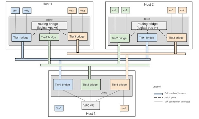 With the understanding of how bridges corresponding to the tiers in VPC are interconnected with a logical router using patch ports lets see how flow rules can be setup to achieve distributed routing and network ACL. There are three different flow configurations on different bridges.
- bridges connected to logical router with patch port
- bridges connected to VPC VR (no patch port)
- bridge corresponding to logical router
Flows rules for the bridges connected to VPC VR (e.g. bridge for tier 1 network on host 3): no new additional flow rules are added to such bridges apart from what is added by OVS tunnel manager currently. Bridge will just act as a mac learning L2 switch with rules to handle broadcast/multicast traffic. To recap from [4] below are the flow rules. there is single table 0 for all the rows.
- priority:1200 :- allow all incoming broadcast (dl_dst=ff:ff:ff:ff:ff:ff) and multicast (nw_dst=224.0.0.0/24) traffic from the VIF's that are connected to the VM's
- priority:1100 :-permit broadcast (dl_dst=ff:ff:ff:ff:ff:ff) and multicast (nw_dst=224.0.0.0/24) traffic to be sent out ONLY on the VIF's that are connect to VM's (i.e excluding the tunnel interfaces)
- priority:1000 :- suppress all broadcast/multicast ingress traffic on GRE tunnels
- priority:0 :- do 'normal' (openflow action) processing on the rest of the flows. this rule will ensure (due to 'normal' action) mac address learning and switching
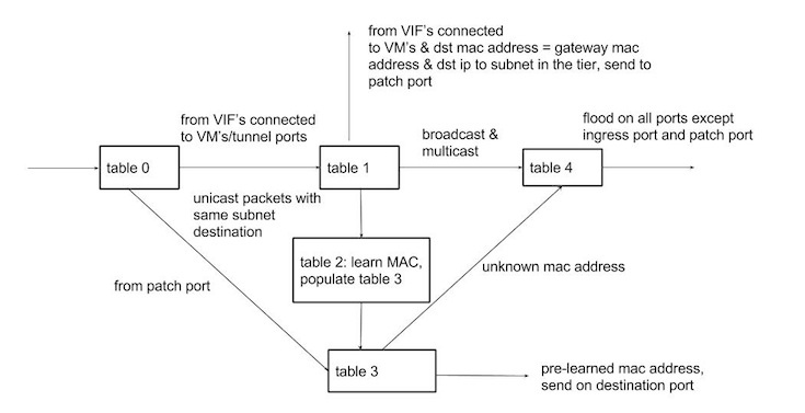
Flows rules for bridge connected to logical router with patch port (e.g. bridge for tier 1 network on host 1): will need additional rules to deal with patch port and ensure:
- explicitly do MAC learning only on VIF's connected to the VM's and on tunnel interfaces. So MAC learning on patch port (to avoid learning the gateway MAC address for the subnet corresponding to tier) is excluded
- for unknown mac address flood packets only on VIF's connected to the VM's and on tunnel interfaces excluding the ingress port and patch port
- on patch port only permit traffic destined to other subnets of VPC and with destination MAC address of gateway for the subnet.
Below diagram depicts the pipeline processing [9] setup with openflow rules.
logical router: Flows rules for bridge acting as logical router:
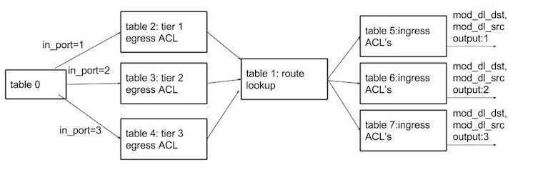
Flows are setup in pipeline processing model as depicted in below diagram, to emulate packet processing on the VPC VR. A default rule with least priority (0) is set in egress ACL's table to drop all packets. Flow rules are added to egress ACL table with high priority (to overrider default rule) to forward packets to lookup table corresponding to egress network ACL's for the tier. Route look up is done in table 1 which is pre populated to resubmit to next level ingress ACL table depending on the destination subnet. A default rule with least priority (0) is set in ingress ACL's table to drop all ingress traffic to a port. Flow rules are added to ingress ACL table with high priority (to overrider default rule) to permit packets corresponding to ingress network ACL's for the tier.
Note: When VPC VR route's packet to destination subnet, it may raise ARP request to get the MAC address of destination VM. VPC VR then forward's the packet with an ethernet header where source mac is gateway's mac address and destination mac is that of destination VM. With logical router though ARP can not be performed, end result is achieved with a flow to modify both source and destination mac address for the flow. A flow rule is required for each VM's in the subnet. Downside with this approach is for each VM created a flow rule need to be added on all hosts on which subnet/tier spans.
Assuming tier1, tier 2 and tier3 has subnets 10.1.1.0/24, 10.1.2.0/24 and 10.1.3.0/24 respectively and corresponding bridges for the tiers are connected to logical routers on openflow ports 1,2,3, flow table would look like below with no ingress and egress rules configured.
table=0,in_port=1 actions=resubmit(,2)
table=0,in_port=2 actions=resubmit(,3)
table=0,in_port=3 actions=resubmit(,4)
table=2, priority=0 actions=drop
table=3, priority=0 actions=drop
table=4, priority=0 actions=drop
table=1,priority=0,nw_dst=10.1.1.0/24 actions=resubmit(,5)
table=1,priority=0,nw_dst=10.1.2.0/24 actions=resubmit(,6)
table=1,priority=0,nw_dst=10.1.3.0/24 actions=resubmit(,7)
table=5, priority=0 actions=drop
table=6, priority=0 actions=drop
table=7, priority=0 actions=drop
Assuming a ingress ACL to permit traffic from tier2, and egress ACL to permit outbound traffic to tier 2 is applied on tier 1 network, below new rules will be added in to flow table of the logical router bridge.
table=2, priority=1000,nw_dst=10.1.2.0/24 actions=resubmit(,1)
table=5, priority=1000,nw_src=10.1.2.0/24 actions=mod_dl_src=mac address for 10.1.2.1, modl_dl_dst=mac address for destination VM,output:1
Packet flows
Lets consider few packet flows to understand how logical router and flow rules achieve distributed routing.
- Consider case where VM1 (assume with IP 10.1.1.20) in tier1 running on host 1, wants to communicate with VM1 (10.1.2.30) in tier 2 running on host 2. sequence of flow would be:
- 10.1.1.20 sends ARP request for 10.1.1.1 (gateway for tier1)
- VPC VR sends ARP response with MAC address (say 3c:07:54:4a:07:8f) on which 10.1.1.1 can be reached
- 10.1.1.20 sends packet to 10.1.2.30 with ethernet destination 3c:07:54:4a:07:8f
- flow rule on tier 1 bridge on host 1, over rides the default flow (normal l2 switching) and sends the packet on patch port
- logical router created for VPC on host 1 receives packet on patch port 1. logical router does route look up (flow table 1 action) and does ingress and egress ACL's and modifies source mac address with mac address of 10.1.2.1 and modifies destination mac address with mac address of 10.1.2.30 and sends packet on patch port2.
- tier 2 bridge on host 1 receives packet on patch port, does a mac lookup.
- if the destination mac address is found, then sends packet on the port else floods packets on all the ports
- tier 2 bridge on host 2 receives packet (due to unicast or flooding on the bridge tier 2 on host1) and forward to VM1.
- Consider case where VM3 (assume IP with 10.1.1.30) in tier 1 running on host 3 wants to communicate with VM1 in tier 2 running on host 2. Sequence of flow would be:
- 10.1.1.30 sends are request for 10.1.1.1
- VPC VR sends ARP response with MAC address (say 3c:07:54:4a:07:8f) on which 10.1.1.1 can be reached
- 10.1.1.30 sends packet to 10.1.2.30 with ethernet destination 3c:07:54:4a:07:8f
- VPC VR receives packet does a route look up, sends packets out on to tier 2 bridge on host 3, after modifying the packets source and destination mac address with that of 10.1.2.1 and mac address at which 10.1.2.30 is present (possibly after ARP resolution)
- tier 2 bridge on host 2 receives packet and forward to VM1.
Key concepts
Above example with just three hosts can be extended to VPC that spans large number of hosts. Here are the basic constructs to generalize to any number of hosts:
- On host that runs VPC VR, nothing need to be changed from the perspective of setting up logical router and flows setup.
- On rest of the hosts on which VPC spans
- irrespective of host has VM from a tier, bridge will be created on the host for each tier in the VPC
- each bridge is setup with full mesh of tunnels with rest of the hosts on which VPC spans
- there is logical router provisioned on each host
- logical router is interconnected to bridges corresponding to the tiers in the VPC through patch ports
- flow rules need to be setup on each bridge to forward the inter-tier traffic to logical router
- flow rules need to be setup on logical router for routing and ACL's
Fall back mechanism
Given the nature of distributed configuration required to setup bridges and flow rules on multiple hosts, there will be windows of time where the configuration is not up to date or as expected to reflect correct VPC network topology. Following principles shall be used to mitigate the impact:
- For eventual consistency, sync mechanism need to be used to keep the configuration of OVS switches and flow rules in consistence with topology (how it spans the physical hosts) of VPC and ingress/egress ACL's applied on the tiers
- wherever possible fall back to data path where packet is sent to VPC VR, so that optimization achieved with distributed routing and network acl's may not leveraged but functionality is not lost because VPC VR will perform ACL and routing anyway.
enable/disable logical router
If the flow rule in the bridge that sends inter tier traffic to go through the patch port to logical router is removed, then traffic will be sent to VPC VR for routing. This fact shall be used to build notion of enable/disable logical router. When a logical router is enabled, flow rule will set on each bridge corresponding to each tier in the VPC to direct inter-tier traffic to logical router. When a logical router is disabled, flow rule set on each bridge corresponding to each tier in the VPC to direct inter-tier traffic to logical router will be removed.
Failure mode
- Failure to set up a full tunnel mesh for VM in a tier shall result in VM deployment failure.
- Failure to setup one or more bridge of the VPC, in full-connected mesh topology shall result in logical router to be disabled
Architecture & Design description
This section describes design changes that shall be implemented in CloudStack management server and OVS plug-in to enable distributed routing and network acl functionality.
API & Service layer changes
- introduce new 'Connectivity' service capability 'distributedrouting'. This capability shall indicate 'Connectivity' service providers ability to perform distributed routing & ACL's.
- createVPCOffering API shall be enhanced to take 'distributedrouting' as capability for 'Connectivity' service.
- Provider specified for the 'Connectivity' service shall be validated with capabilities declared by the service provider, to ensure provider supports 'distributedrouting' capability.
- listVPCOfferings API shall return VpcOfferingResponse response that shall contain 'Connectivity' service's 'distributedrouting' capability details of the offering if it is configured
- createNetworkOffering API shall throw exception if distributedrouting' capability is specified for 'Connectivity' service.
OVS Network Element enhancements
- OVS element shall declare 'distributedrouting' as supported capability for 'Connectivity' service.
- OvsElement uses prepare() phase in NIC life cycle to implement tunnels and setup bridges on hypervisors. Following changes shall be needed in nic prepare phase:
- current logic of preparing a NIC is described as below, if the VM's is first VM from the network being launched on a host.
- get the list of hosts on which network spans currently
- create tunnel from the current host on which VM being launched to all the host on which network spans
- create tunnel from all the host on which network spans to the current host on which VM being launched
- check shall be made if network is part of VPC, if its part of VPC, and VPC offering does not have 'distributedrouting' capability enabled current flow of actions outlined above shall be performed during the nic prepare phase
- if network is part of VPC, and VPC offering has 'distributedrouting' capability enabled then following actions shall be performed.
- if there is VPC VR running on the current host on which VM is being launched then proceed with steps outlined above (i.e setting up tunnels just with the bridge corresponding to network).
- if VPC VR is running on different host than the current host on which VM is being launched, then following actions shall be performed:
- for each network in the VPC create a bridged network
- for each of the bridge created for the tier in the VPC, form full mesh of tunnels with the hosts on which network/tier spans
- create a bridge that shall act as logical router and connect each bridge created in previous step with patch port to logical router
- set up flow rules on each bridge to;
- exclude mac learning and flooding on patch port
- for traffic destined to other tiers send the traffic on the patch port
- for the rest of the traffic from VIF's connected to VM, tunnel interface and patch port do normal (L2 switching) processing
- set up flow rules on logical router bridge to:
- reflect flows corresponding to current ingress ACL's and egress ACL's set on tier
- set flows to route traffic on appropriate patch port based on the destination ip's subnet
- OvsElement release() (which handles NIC release) is currently used to destroy tunnels and bridges on hypervisors. Following changes shall be needed in nic release phase:
- current logic of releasing a NIC is described as below, if the VM's is last VM from the network being deleted on the host.
- get the list of hosts on which network spans currently
- delete tunnel from all the hosts on which network spans to the current host on which VM being deleted
- destroy the bridge
- check shall be made if network is part of VPC, if its part of VPC, and VPC offering does not have 'distributedrouting' capability enabled current flow of actions outlined above for release phase shall be performed during the nic release
- if network is part of VPC, and VPC offering has 'distributedrouting' capability enabled & VM is not the LAST vm from VPC then just return
- if network is part of VPC, and VPC offering has 'distributedrouting' capability enabled & VM is LAST vm from the VPC on the host then following steps shall be performed
- for each network/tier in the VPC:
- get the list of hosts on which tier spans
- delete tunnels from the all the hosts on which tier spans to the current host on which VM is being deleted
- destroy the bridge for the tier
- destroy the logical router
- OvsElement implement() that handles implement phase of network shall need following changes to deal with case where a new tier in a VPC is created:
- check shall be made if network is part of VPC, if its part of VPC, and VPC offering have 'distributedrouting' capability enabled then
- get the list of hosts on which VPC spans currently excluding host running VPC VR
- for each host in the list
- create a bridge for the tier
- interconnect the bridge and logical router by creating a patch port on the logical router and the created bridge
- add flow rule to forward packets on the created patch port on the logical router for IP packets destined to subnet corresponding to created tier
- OvsElement destory() that handles destroy phase of network shall need following changes to deal with case where a tier in a VPC is deleted:
- check shall be made if network is part of VPC, if its part of VPC, and VPC offering have 'distributedrouting' capability enabled then
- get the list of hosts on which VPC spans currently excluding host running VPC VR
- for each host in the list
- destroy the bridge corresponding to the network
- destroy the patch port on logical router
- remove the forwarding entry flow and entries corresponding to ingress, egress ACL's
- VPC VR migration: OvsElement shall implement NetworkMigrationResponder to hook into VM migration. If the VM that is being migrated is VPC VR, and VPC offering have 'distributedrouting' capability enabled then following action shall be performed
- On the host from which VPC VR is being migrated
- create a logical router, connect it with the bridges corresponding to tiers with patch ports
- populate flow rules on logical router to reflect ingress and egress ACL for each tier
- populate flow rules on logical router to forward packet on destination patch port depending on the destination IP
- on each bridge establish flow rules to forward inter-tier traffic on to patch port
- replaceNetworkACLList enhancements:
- OvsTunnel manager shall subscribe to replaceNetworkACLList events using in-memory event bus
- on event trigger, if the VPC offering of the VPC that contains the network, has 'distributedrouting' capability enabled then following actions shall be performed
- get the list of the hosts on which network spans
- on each host flush the ingress/egress ACL represented as flows on logical router bridge and apply new flows corresponding to the new ACL list
OVS topology guru
Notion of VPC topology guru shall be introduced. Which shall subscribe to VM start/stop/migrate events, network life cycle events, VPC life cycle events, host connect/disconnect events to build below knowledge
- hosts on which a network (for tier in VPC) spans
- hosts on which VPC spans (cumulative of host on which individual tier's in VPC spans)
- list of VPC's that span on the host
OVS tunnel manager enhancements
OvsTunnel manager shall be enhanced with following functionalities;
- keep track of state of the tunnels for a network between two hosts for a tier in VPC
- state of logical router on a host for a VPC
- function to tell if 'logical router' can be enabled on a host for a VPC
- enable logical router on a host for VPC
- disable logical router on a host for VPC
- back ground thread that periodically performs
- get the list of VPC's that has distributed routing enabled
- for each VPC in the list
- get the list of hosts on which VPC spans
- check the state of tunnels from the host and toward the host
- if the tunnel is not established attempt to establish tunnel
- if all the tunnels established enable logical router
resource layer commands
Following new resource layer commands shall be introduced.
- OvsCreateLogicalRouter: command to setup logical router on the hypervisor. shall contain following details details of subnet of each tier, gre key assigned for the tier and VPC id. following actions shall be performed by resource layer
- derive logical router name from the vpc id, and create bridge with generated name
- for each tier
- from the gre key form the network name and find the network
- get the bridge of the network, create a patch ports to connect logical router with the bridge
- add flow on the logical router to send traffic bound to the subnet on the created patch port for the tier
- OvsDeleteLogicalRouter: command to delete logical router on the hypervisor.shall contain following details details of subnet of each tier, gre key assigned for the tier and VPC id. following actions shall be performed by resource layer
- derive logical router name from the vpc id, and find the bridge with generated name. delete the bridge.
- for each tier
- from the gre key form the network name and find the network
- get the bridge of the network, delete patch port
- delete flow to send traffic bound to the subnet on the patch port for the tier
- OvsUpdateLogicalRouter
- add/remove a tier from the logical router
- enable/disable distributed routing and acl's
- OvsCreateFlowCommand: adds a flow to bridge
- OvsDeleteFlowCommand: deletes a flow from the bridge
script enhancements
Ovstunnel script shall be enhanced with following methods
- setup_logical_router
- destroy_logical_router
- enable_logical_router
- disable_logical_router
troubleshooting
To aid trouble shoot in case of connectivity or network acl functionality issues when VPC is enabled with distributed router, an admin API shall be introduced in OVS plugin that shall expose below details maintained by OVS topology guru and OVS tunnel manager
- list of hosts on which VPC spans
- state(enabled/disabled) of logical router on a host for the VPC
- state of tunnels between the hosts for a tier in the VPC
UI changes
- createVpcOffering APi shall have ability to create VPC offering with 'distributedrouting' as connectivity service capability. No UI is needed for this change (unless there is plan to add UI for createVpcOffering) since there is no UI for VPC offering creation itself.
- In the VPC details view, there shall be action to view the current state of tunnel between the hosts on which VPC spans
Convergence time
Following are the events that require state update of configuration and corresponding latency:
- on first VM launch/ last VM destroy on a host need setting up/destroy tunnel mesh for each tier's bridge with rest of the hosts. Latency to replicate configuration is proportional to (n*(n-1))/2 * m where n is the number of hosts on which VPC spans and m is the number of tiers in the VPC. n*(n-1)/2
- on VPC tier create/delete, needs setting up/destroy of bridge for the tier on all the hosts and setting up tunnel mesh. Latency is proportional to n * n-1/2 where n is number of hosts on which VPC spans + setting up the router entry on logical router
- on replace network ACL for a tier needs update of acl table on logical router on each host.
Performance and scaling issues
- For distributed routing there is a logical router created and bridge for each tier irrespective of the fact VM from tier is running on hypervisors or not. Given that current hypervisors can run VM's in the magnitude of hundreds clearly for the proposed distributed routing solution require creating bridges in same magnitude in the worst case. Maximum number of switches that can be supported by OpenVswitch depends on the maximum number of file descriptors configured [7]. So maximum number of bridges that can be created on hypervisor should not be a concern.
- Maximum number of flows that can applied to a switch is only limited by memory available [7]. There is no hard limit on the maximum number of flows that can be configured on a switch.